

How To Register Laser Cutter
![]()
Universal Camera Registration
The Universal Camera Registration (UCR) option features a camera that locates and determines the exact positions of registration marks on materials inside the laser arrangement. Software adjusts the predefined cutting-path to fit the textile. A laser system user simply places material shut to the correct position in the light amplification by stimulated emission of radiation system, and the UCR automatically makes adjustments to the cutting-path to fit the material where it is placed.
- Infrequent Processing Accuracy
Universal Photographic camera Registration tin can essentially increase process accuracy and repeatability without the need for complex fixturing. - Enhanced Productivity
Congenital in tools to back up both single bicycle processes, and automation capabilities for higher volume manufacturing. - Intuitive User Interface
The process of setting up and running camera registration is simple, intuitive, and requires only minimal training.
-
Exceptional Processing Accuracy
Many laser material processing tasks require alignment with features on the material. There are several examples of this such as print-cut where the laser system is used to cut out a feature on the textile later it has been through a printing process. In these types of applications users often turn to constructing mechanical fixtures to hold the role or cloth in a specific location and marshal the light amplification by stimulated emission of radiation process to that fixture.
Mechanical fixturing solutions are adequate for some visual applications but have several drawbacks. They can be both time consuming and expensive to create. Aligning the procedure to the fixture, setting proper focus, allowing adequate ventilation for byproduct removal, and ensuring that the fixture does not interfere with the laser systems moving components can all be error prone tasks. Additionally, if the process is to be repeated in the future, fixtures must be stored and the operator must go through the setup process each time.
Universal Camera Registration (UCR) reduces the need for mechanical fixtures while simultaneously providing higher accuracy and repeatability. UCR uses a loftier resolution camera inside of the organisation carriage to visually identify features on the part to be processed corresponding to registration marks within the design file. This data is used to align the design file to the material.
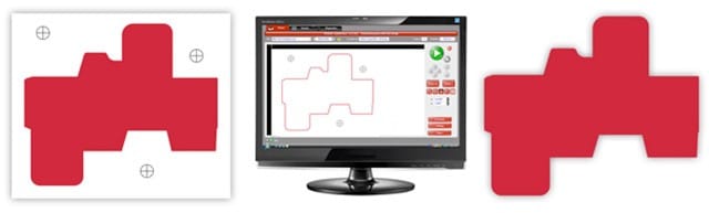
From left to right- Raw fabric with registration marks, the UCR software recognizing these locations, and the final cutout
UCR can compensate for a broad variety of pre-process and fabric distortions which typify manufacturing processes which precede laser material modification. Specifically, UCR can adjust the following to ensure nearly perfect registration between the geometry of the material and laser process:
- Translation
Relocating the blueprint file on the 10-Y aeroplane. This is the most common aligning when the material is placed into the system by manus. This function can be accomplished with a single registration mark.
- Rotation
Rotation of the pattern file on the 10-Y plane. Rotation requires at least two registration marks on the fabric and is frequently necessary when materials are placed into the organization by paw. This is an important compensation mechanism since even a few degrees of rotation misalignment tin crusade serious processing issues.
- Scale
Irresolute the size of the design file to match the textile. Behind Translation and Rotation, Scale can be a major correspondent to misalignment. Materials such as paper, sparse films and fabrics frequently stretch when handled and besides change size with temperature and humidity. If left uncompensated, these can cause misalignments which can be hands seen by the naked heart. To conform the scale, at least 2 registration marks are required.
- Skew
Adjustment of the bending betwixt the X and Y axis. Skew is more subtle than any of the previous distortions however, and for the highest precision and quality, it cannot exist ignored. Coil processes such as kickoff press tin cause shear distortions to occur if the rollers are not perfectly uniform in diameter or if the incoming material is stretched on one side relative to another. UCR requires at least three registration points to perform skew compensation.
- Perspective
An adjustment on the 3D point of view of the design file. Perspective aligning is required for the highest precision applications. While less common, several manufacturing processes can generate perspective manner distortions on the fabric and, if non properly deemed for, can fail to meet tight tolerance specifications.
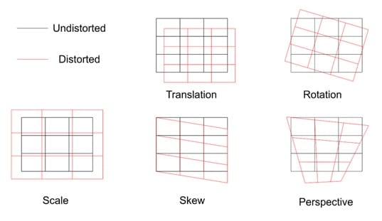
A diagram illustrating the various types of distortions which tin be nowadays on materials prior to processing with the laser system. UCR is capable of accommodating all of the higher up distortions and any combination thereof.
- Translation
-
Enhanced Productivity
Flexible Registration Mark Types
The UCR allows the user to select from a variety of standard registration marks such as crosshairs and circles. When a blueprint file is generated with these types of marks, the system tin can automatically identify them on the material leading to both loftier productivity and flexibility.
In addition to the set of standard registration marks, UCR can use virtually whatever feature on the part as a betoken of registration. For case, if a process is to be performed on a printed excursion board, then any feature on that lath can be used every bit a registration point: the centre of a screw hole, a small capacitor, a via pigsty, or a conductive trace.
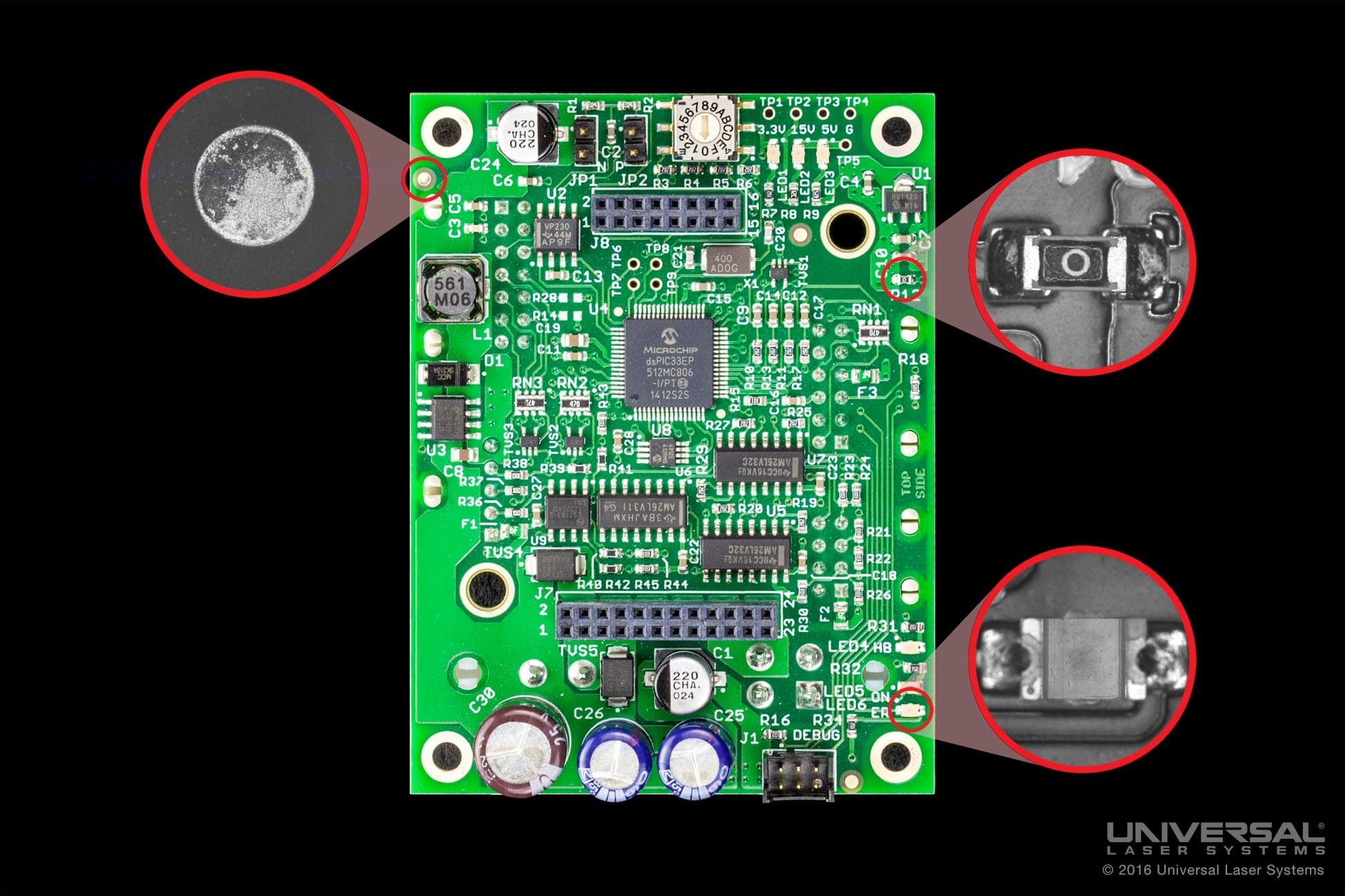
UCR utilizing unlike components on a circuit board equally registration points
Manual and Automatic Registration Modes
UCR provides manual and automatic modes for aligning design files to materials. The manual method is useful for processing a relatively pocket-sized number of parts. In this style, the user selects the location of each registration marker as seen through the photographic camera. Once all of the locations take been acquired, the process may continue equally usual.
In automatic mode the user simply selects the center location of each registration mark through the interactive software to train the laser system on each registration marking. The UCR volition and then capture an image of those marks and shop them for later use. Each time a new instance is placed in the machine (used as a laser cutter, laser engraver, light amplification by stimulated emission of radiation marker, or a combination of such), the UCR automatically recalls the images and locates them using the onboard photographic camera. Automatic mode is useful in batch production where several parts must exist produced at a time.
Process Duplication
Often times at that place will be multiple parts on a single fabric each requiring compensation by the UCR. In these instances, the duplication characteristic within the Universal Control Panel or Light amplification by stimulated emission of radiation System Managing director can be used to repeat the registration process across an array of parts. This will marshal the blueprint file of each office perfectly generating extremely loftier quality processing on each instance.
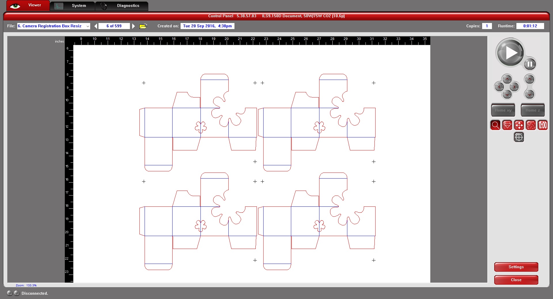
The Light amplification by stimulated emission of radiation System Software with four copies of a single photographic camera registration process generated past duplication
-
Intuitive User Interface
Camera registration is a powerful and flexible tool, only is still like shooting fish in a barrel to use. A typical workflow follows a basic pattern:
- The design file is created along with registration marks. These are points that lucifer up to features on the pre-fabricated cloth. These can be whatsoever feature on the cloth which is hands recognizable by the onboard photographic camera.
- The cloth is inserted into the laser system.
- The laser system uses the camera to find all of the registration marks on the textile.
- The light amplification by stimulated emission of radiation organization calculates the correct displacement, rotation, scale, skew, and perspective of the user's material.
- The cut or mark paths are corrected to fit the textile and the material is processed.
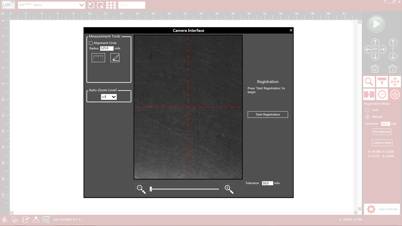
The UCR user interface showing the registration alignment action
DISCOVER
© 2022 Universal Laser Systems, Inc. All rights reserved. Universal Laser Systems logo and name are registered trademarks of Universal Laser Systems, Inc. All other company and product names are trademarks or registered trademarks of their respective companies.

How To Register Laser Cutter,
Source: https://www.ulsinc.com/discover-uls-innovations/universal-camera-registration
Posted by: morrellwhithen1967.blogspot.com
0 Response to "How To Register Laser Cutter"
Post a Comment